How: Designing a fully CNC-Processed Cashwrap
Big Impact. Low Cost.
Some Assembly Required

Abstract
By marrying the power of modern CAD-CAM software with the relative low cost of CNC (computer numeric control) "plate processing", it is getting easier to create freeform elements within bespoke spaces that were not practical a decade ago. Using low cost and user-friendly mechanical CAD (MCAD) to explore design directions and generate output files that are fed directly to manufacturing equipment, it is possible to tightly control the look of a piece without turning to expensive dedicated fixture vendors. Additionally, this kind of work can be very quickly quoted because the quoting process itself is computer assisted. The process can be employed on a range of metals including multiple alloys of steel, stainless steel and aluminum. Finally, using similar techniques, planer wooden elements can be introduced into metal assemblies as needs and aesthetics dictate.
Two processes, Endless Possibilities
Modern high definition gantry laser cutting tables are changing the landscape of production and fabrication. Thanks to automation, the cost of “processing” steel plate has become relatively inexpensive and the capabilities are increasing. With just two widely available fabrication processes: laser cutting and traditional brake-forming, it’s possible to make almost any shape you can think of --without any secondary high skill operations such as welding.. The basic workflow is as follows:
I used Fusion-360 to ideate various design concepts. Once finalized, I generated a full assembly model and, critically, employed the software’s flat pattern command to “unfold” the shape into a 2D file that could be cut on a laser table. To create an accurate flat pattern, the software tracks and anticipates the stretching and compressing of the steel as it undergoes bending in a press brake. The amount of growth or shrinkage in the pattern is governed by a property of the material called the K-factor.

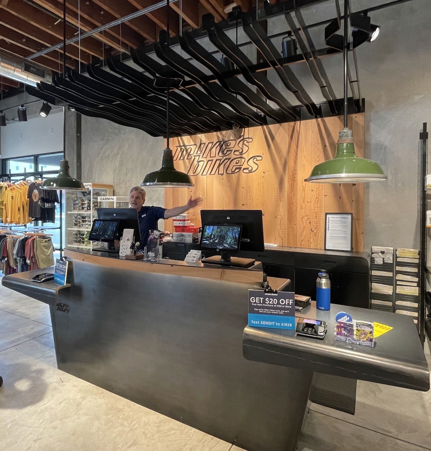
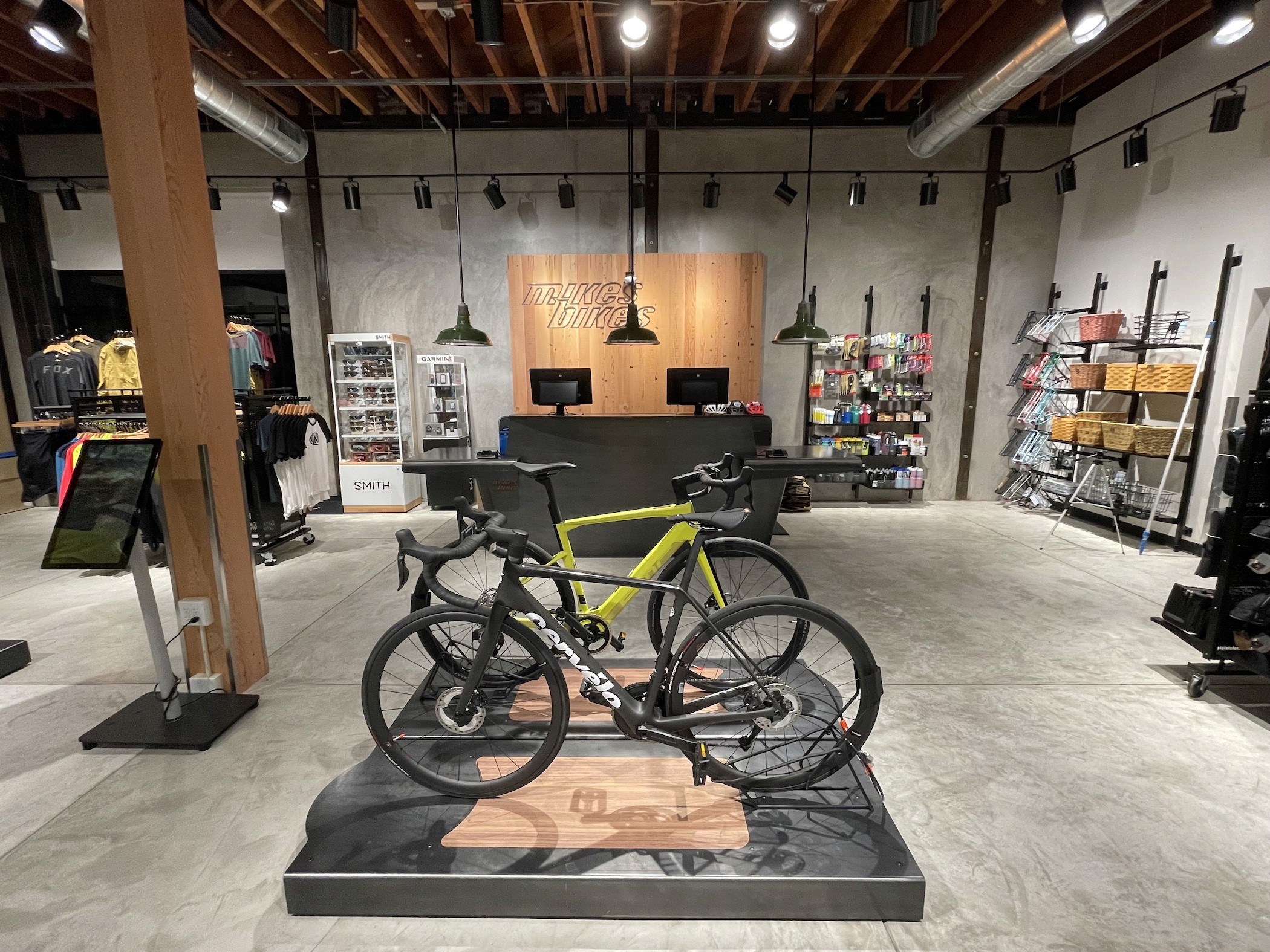
I exported the 2D drawing out to a CAD interchange format that can be read by the plate processing house.. They imported the CAD file to their machine and cut out the shape including all holes, notches, etc.. This particular project was processed at Lehman Manufacturing, a 3rd generation fabricator in Fresno California on their new 30 kilowatt nitrogen gantry laser. The table can process sheets over 6ft wide by 20ft long (2m x 6.1m).. The resulting parts are accurate to within a few thousands of an inch. We did a test on the new machine to check for “melt out” on some of the finer bridgework on this logo:

Here’s what the machine looks like in operation. Though it doesn’t seem fast in video, it is scary fast in person and makes you jump out of the way when the cutting head races toward the front of the table.
The software also places precise bend-line centers on the 2D files which then get dimensioned and fed into the press brake. Regardless of how accurate the drawings and dimensions are, bending plate steel is as much an art as a science and there is no technical substitute for a skilled press brake operator. Frequently, tests will be performed on smalls strips of identical thickness material.
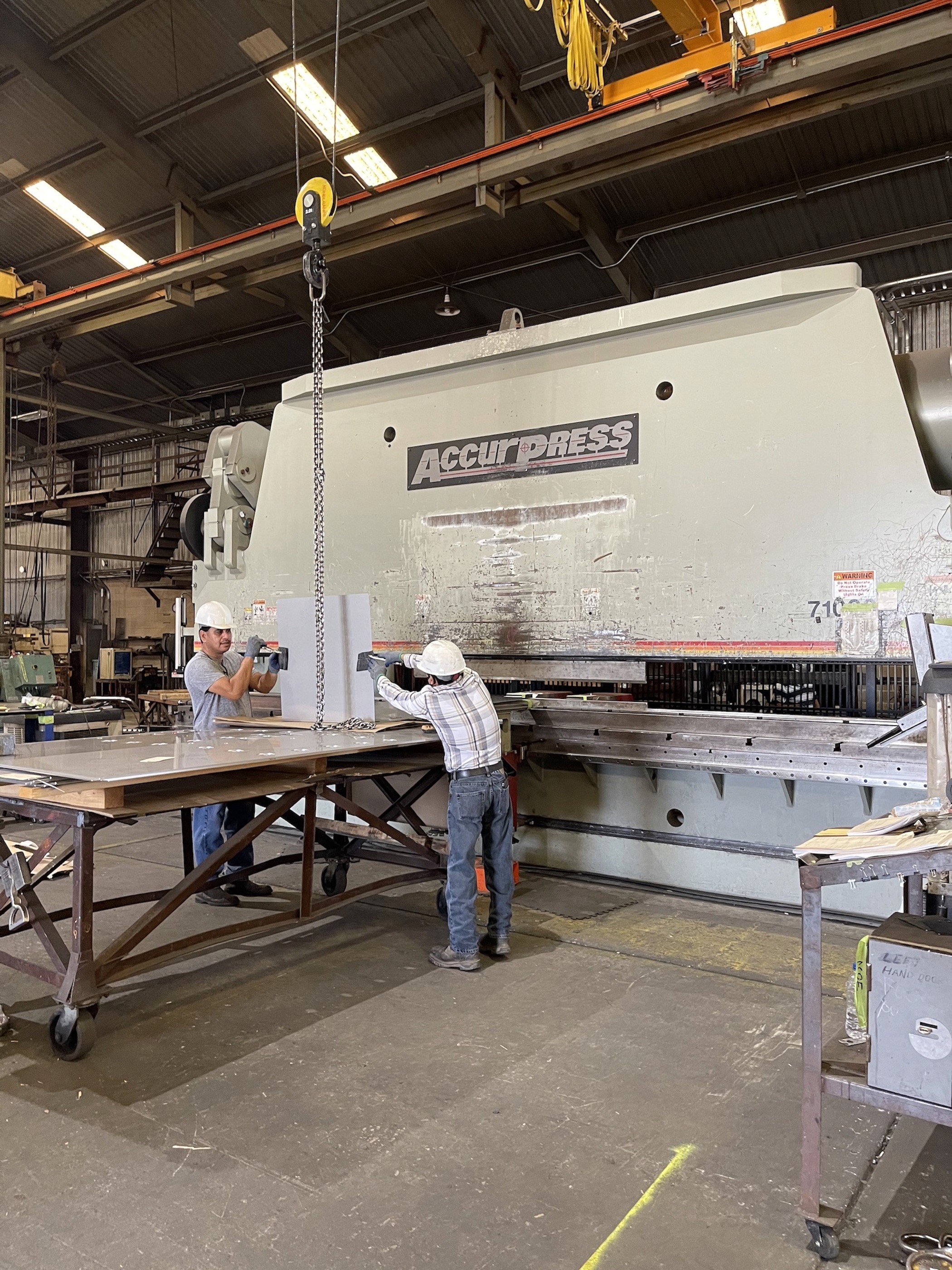
The forming dies for a 1K ton machine like this are a significant investment beyond the cost of the machine itself (a single set of dies can run to six figures USD) so you need to use caution when designing with non-standard bends. In this case I wanted to use large radius bends at the distinctive sloping corners of the cabinet’s carcass. I contacted Lehman's in advance to get a list of available tooling and chose to design around a 4.25” diameter (10.8cm) half round die they had on hand. This is the press brake that the cashwrap carcass was formed on. It can form 1” (2.5cm) plate steel at a length of 20 ft (6.1m). In this project I formed the transaction tops from massive 3/4" (1.9cm) plate steel. The carcass itself was made from 5/15” (8mm) plate.
And this is what the carcass looked like off the truck and once I got the base assembled and bolted together. The single carcass piece alone weighs over 400 pounds (181 kg). In the pictures below you can see the flanges with holes used to bolt the cashwrap to the floor. Note also the integrated hex nuts inserted into the base to accept 1/2-13 set screw leveling bolts.

I used a materials lift to rotate the carcass and base into position. It was important to do this relatively early in the process because the combined weight of the remaining assembly would exceed the material lift's rating. Once the rest of the carcass was rotated to vertical and the remaining components added, the unit could be safely moved with a pallet jack.
The wooden components of the cashwrap were also designed as part of the same assembly file in Fusion 360 and sent to another vendor to be cut on a large CNC router table. They fit into the steel and to each other like puzzle pieces.